Written By: Don Dodi
Fact Checked By: Kristen Brown
Reviewed By: Diego Rosenberg
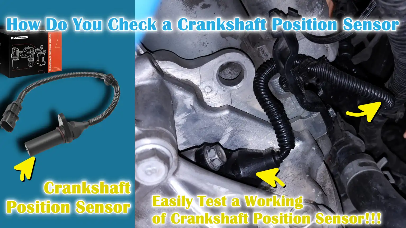
Did you know that: many no-start and stalling problems often begin with a faulty crankshaft sensor, as it is really important sensor in modern vehicle as it literally tells the engine computer exactly where the crankshaft is and how fast it is spinning.
So, this information actually helps the engine control unit: ECU, to decide when to inject the fuel and when to spark the spark plugs.
That’s why, if it is not working properly then without the correct data from this sensor, the engine may even fail to start, stall suddenly, misfire or even it can run in very poor way.
And, there’s automotive engineering standards that shows that almost every fuel-injected engine relies on the crankshaft position sensor for their accurate ignition timing and having smooth engine operation as well.
Not only this, over the period of time, usage, heat, oil contamination, vibration and electrical wear that can lead it to damage the sensor or its wiring as well.
Which is why, we have come up with this guide on How Do You Check a Crankshaft Position Sensor, so that you can properly check and diagnose the engine problems early to avoid any unnecessary future repairs.
What are the Symptoms of a Faulty Crankshaft Position Sensor
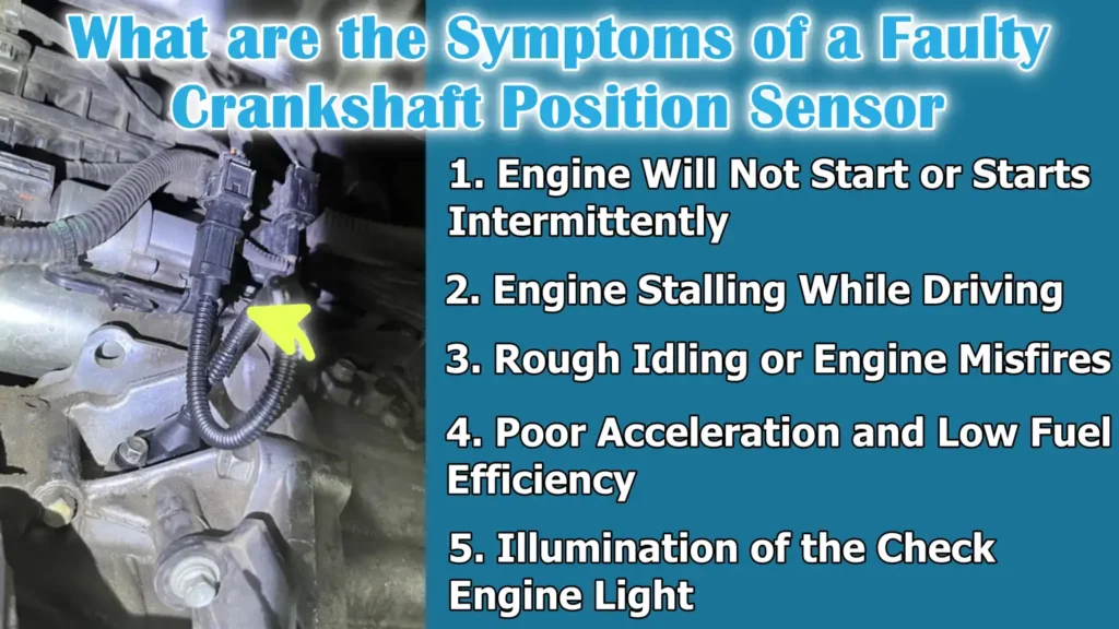
1. Engine Will Not Start or Starts Intermittently
When a crankshaft position sensor begins to fail, one of the most common problems is that the engine may not start at all or may only start intermittently.
This is because the engine computer relies on this sensor to know the precise position and speed of the crankshaft before initiating fuel injection and spark.
If the sensor sends no signal or an incorrect signal, the ECU cannot properly time the ignition, so the engine may crank but refuse to start.
In some cases, the car may start when cold and fail when warm, as heat can damage the sensor internally.
2. Engine Stalling While Driving
A faulty crankshaft position sensor can cause the engine to suddenly stall while driving, even at highway speeds.
This happens when the sensor temporarily loses its signal or sends incorrect data to the engine computer.
When the ECU loses track of the crankshaft position, it may shut off the fuel supply or ignition for safety reasons, causing the engine to shut down immediately.
Sudden engine stalling is dangerous as it can result in the loss of power steering and braking assistance, specially at low speeds or in traffic.
3. Rough Idling or Engine Misfires
When the crankshaft position sensor fails to provide accurate timing information, the engine may experience rough idling or misfires.
Rough idling occurs because the fuel injection and spark timing become irregular, causing the engine to shake or vibrate more than usual.
Misfires can be felt as jerks, hesitations, or an uneven engine sound.
Over time, persistent misfiring can lead to increased engine wear and damage to components such as spark plugs and the catalytic converter.
4. Poor Acceleration and Low Fuel Efficiency
A faulty crankshaft position sensor can cause weak or sluggish acceleration.
As, the engine computer uses the sensor data to adjust fuel supply and ignition timing, incorrect readings can prevent the engine from generating the correct power when the accelerator is pressed.
This incorrect timing also leads to incomplete fuel combustion, resulting in increased fuel consumption.
Consequently, the vehicle may feel sluggish and require more fuel to travel the same distance.
5. Illumination of the Check Engine Light
When the crankshaft position sensor sends incorrect signals or stops working, the engine control unit (ECU) often detects the problem and illuminates the check engine light.
The ECU stores trouble codes related to the crankshaft position sensor’s performance, signal loss, or circuit faults.
While the check engine light alone doesn’t pinpoint the exact problem, if it’s accompanied by other issues such as engine stalling or difficulty starting, it’s a strong indication that the sensor or its wiring should be checked as soon as possible to prevent further engine problems.
Tools
| Tool or Equipment | Purpose and Simple Explanation |
|---|---|
| OBD-II Diagnostic Scanner | This tool connects to the car’s computer and reads the error codes. It helps identify crankshaft sensor problems by displaying fault codes and warning messages stored in the system. |
| Digital Multimeter | A multimeter measures voltage, resistance and signal output from sensors. This helps confirm whether the sensor is working correctly or if it is sending a weak or no signal. |
| Basic Hand Tools | Tools such as a ratchet, socket and screwdriver are used to access and remove the sensor. These tools are also needed to loosen the cover and safely disconnect the connector. |
| Vehicle Service Manual or Wiring Diagram | This guide shows the correct sensor locations and test values. It helps prevent errors by providing model-specific information. |
| Safety Gloves and Eye Protection | These protect the hands and eyes from dirt, sharp objects and hot engine parts. Safety gear reduces the risk of injury during testing. |
How to Take Care of Safety Before Testing
1. Parking the Vehicle on a Level Surface
Before testing the crankshaft position sensor, the vehicle should always be parked on a level and stable surface.
A level surface prevents the vehicle from rolling or shifting while you are working near the engine or underneath the vehicle.
This is specially important if the sensor is located near the crankshaft pulley or transmission area.
Parking on level ground provides stability and clear visibility, reducing the risk of slips or sudden vehicle movement during inspection.
2. Turning Off the Engine and Disconnecting the Battery
The engine must be completely turned off before beginning any testing.
Disconnecting the battery, specifically the negative terminal, prevents accidental electrical shocks and protects the vehicle’s electronic control unit from damage.
The crankshaft position sensor operates within the engine’s electrical system and testing it with the battery connected can lead to short circuits or inaccurate readings.
Disconnecting the battery also eliminates the risk of the engine unexpectedly starting while your hands are near moving parts.
3. Allowing the Engine to Cool Down
Engines can become extremely hot during operation and many crankshaft position sensors are located near hot engine parts.
Allowing the engine to cool down completely prevents burns and makes handling the parts safer and more comfortable.
Heat can also affect electrical readings, so testing a cool engine yields more accurate results.
Waiting for the engine to cool is a simple step that improves both safety and the reliability of the testing.
4. Wearing Appropriate Safety Equipment
Before working on any engine sensor, it is essential to wear basic safety equipment such as gloves and eye protection.
Gloves protect hands from sharp edges, oil and grime, while eye protection shields against dust and debris.
Even simple testing tasks can involve accidental contact with moving or dirty parts.
Using the correct safety equipment reduces the risk of injury and allows you to perform your work with greater confidence and focus.
How to Locate the Crankshaft Position Sensor
1. Common Sensor Locations
The crankshaft position sensor is typically mounted very close to the crankshaft to accurately read its position and speed.
In many vehicles, this sensor is located near the crankshaft pulley at the front of the engine, where it reads the movement of a toothed wheel or timing ring.
In some designs, it’s located near the flywheel or flexplate at the rear of the engine, particularly in rear-wheel-drive vehicles.
Other engines mount the sensor directly on the engine block, positioned to detect crankshaft rotation via a magnetic or electronic signal.
Knowing these common locations helps narrow the search and avoids unnecessary removal of parts.
2. Variations in Sensor Location Based on Vehicle Type
The exact location of the crankshaft position sensor can vary significantly depending on the engine layout, drivetrain type and manufacturer design.
Front-wheel-drive vehicles often have the sensor mounted low on the engine block or near the transmission housing.
Rear-wheel-drive vehicles typically have it located near the flywheel area.
Some modern engines utilize multiple sensors, while others integrate the sensor into compact engine designs that may require removing covers or surrounding components for access.
These variations mean that guessing the location can waste time or lead to accidental damage.
3. Using the Service Manual to Find the Correct Location
The most reliable way to locate the crankshaft position sensor is to consult the vehicle’s service manual or official wiring diagrams.
These resources provide accurate diagrams, mounting points and connector details specific to the engine model.
The manual will also indicate if any special tools or steps are required to safely access the sensor.
Using the service manual reduces the risk of misidentifying the sensor and ensures correct handling, making the entire inspection process faster, safer and more reliable.
How to Perform Visual Inspection of the Sensor
1. Checking for Damaged Wiring or Loose Connectors
A visual inspection should always begin with a careful examination of the wiring and connectors associated with the crankshaft position sensor.
Over time, engine heat, vibration and movement can cause wires to fray, chafe, or break internally.
Loose or partially connected connectors can interrupt the sensor signal, leading to starting problems or engine stalling.
Even minor wiring issues can prevent the sensor from sending accurate information to the engine computer, so checking for tight, clean and undamaged connections is crucial.
2. Checking for Buildup of Oil, Dirt, or Metal Debris
The crankshaft position sensor is often located in areas where oil leaks, road grime and metal particles can accumulate.
Buildup of oil and dirt can interfere with the sensor’s ability to accurately read crankshaft movement.
Metal debris, specially on magnetic sensors, can cling to the sensor tip and distort the signal.
This contamination can lead to inaccurate readings or signal loss, resulting in poor engine performance.
Cleaning any visible debris and identifying the source of the contamination can prevent recurring sensor problems.
3. Looking for Physical Cracks or Corrosion
Physical damage is another common cause of crankshaft position sensor failure.
Cracks can develop in the sensor body due to engine vibration or improper installation.
Corrosion on the sensor or connector pins can disrupt electrical flow and weaken the signal sent to the engine control unit.
Exposure to moisture, specially in older vehicles, often leads to corrosion.
Any visible cracks, rust, or corrosion are strong indicators that the sensor is no longer functioning reliably and may need to be replaced.
How to Test the Sensor Using an OBD-II Scanner
1. Connecting the Scanner to the Vehicle
To test the crankshaft position sensor with an OBD-II scanner, first connect the scanner to the vehicle’s diagnostic port.
This port is usually located under the dashboard on the driver’s side.
Once connected, the scanner communicates directly with the engine control unit (ECU) and retrieves stored engine data.
This step is crucial because modern vehicles rely heavily on electronic monitoring and the ECU immediately records problems as soon as the sensor signal malfunctions.
2. Reading Trouble Codes Related to the Crankshaft Sensor
After connecting the scanner, the next step is to read the trouble codes stored in the engine computer.
These codes act as digital messages that indicate what the ECU is detecting.
When the crankshaft position sensor is faulty, the ECU often records signal errors, missing signals, or timing issues.
Reading these codes helps confirm whether the sensor itself is defective or if the problem might be related to wiring or signal interference.
3. Common Error Codes P0335 to P0339
Crankshaft position sensor problems are commonly associated with error codes in the P0335 to P0339 range.
These codes typically indicate issues such as no sensor signal, weak signal, incorrect timing, or intermittent signal loss.
Each code points to a specific type of sensor or circuit problem, helping to pinpoint the cause of engine starting difficulties, stalling, or misfiring.
Understanding this code range makes diagnosis faster and more accurate.
4. Clearing Codes and Retesting After Repair
Once testing or inspection is complete, clearing the stored codes is an essential final step.
Clearing the codes resets the engine computer, allowing it to monitor the sensor again from a clean state.
After clearing the codes, the vehicle should be started and driven for a short period to see if the codes reappear.
If the same crankshaft sensor codes return, it confirms that the problem still exists and further repairs or sensor replacement may be necessary.
How to Test the Crankshaft Position Sensor with a Multimeter
1. Identifying the Sensor Type
Before testing the crankshaft position sensor, it’s crucial to identify whether the vehicle uses a magnetic sensor or a Hall-effect sensor.
Magnetic sensors typically have two wires and generate their own signal as the crankshaft rotates.
Hall-effect sensors typically have three wires and require a power supply from the engine computer to function.
Identifying the correct type is essential because each sensor operates differently and must be tested accordingly to avoid inaccurate results.
2. Measuring Resistance for Magnetic Sensors
For magnetic crankshaft position sensors, resistance testing is a crucial diagnostic step.
By setting the multimeter to resistance mode, the sensor’s terminals are tested to determine if the electrical flow is within the normal range.
A properly functioning magnetic sensor will display a stable resistance value, while a faulty sensor may show no reading or a value that is too high or too low.
If the resistance is outside the normal range, the sensor will be unable to generate a reliable signal during engine cranking or operation.
3. Checking Voltage Supply and Signal Output for Hall-Effect Sensors
Hall-effect crankshaft position sensors require an external voltage supply, typically provided by the engine control unit.
With the multimeter set to voltage mode, a steady voltage should be present on the power supply wire when the ignition is on.
The signal wire should show a fluctuating voltage when the engine is cranking or running.
If the sensor is not receiving power or is not sending a fluctuating signal, the engine computer will be unable to accurately track the crankshaft position, leading to starting or running problems.
4. Comparing Readings to Manufacturer Specifications
All test results should be compared to the values provided in the vehicle’s service manual.
Each engine design has specific resistance and voltage ranges that define normal operation.
A sensor may appear to be functioning, but it could still be operating outside the approved range, leading to engine problems.
Comparing the readings to the manufacturer’s specifications ensures an accurate diagnosis and helps confirm whether the sensor is truly faulty or if the problem lies elsewhere in the electrical system.
How to Test Sensor Signals While Cranking the Engine
1. Setting the Multimeter to AC or DC Voltage
When testing the crankshaft position sensor while cranking the engine, it’s crucial to set the multimeter to the correct voltage mode.
Magnetic sensors produce an alternating signal, so the multimeter should be set to AC voltage.
Hall-effect sensors produce a digital signal that switches between on and off, so the multimeter should be set to DC voltage.
Using the correct setting ensures that the reading accurately reflects the actual sensor output and prevents confusion caused by using the wrong measurement mode.
2. Observing Signal Fluctuations While Cranking the Engine
As the engine cranks, the crankshaft begins to rotate and the sensor should produce a changing voltage signal.
On a functioning sensor, the multimeter display will show a voltage that gradually increases and decreases or switches between values as the engine rotates.
These signal changes confirm that the sensor is detecting the crankshaft’s movement and sending information to the engine control unit.
Consistent and repeatable signal fluctuations typically indicate a healthy sensor.
3. Identifying Abnormal or No Signal Conditions
If the multimeter shows no voltage changes while cranking or displays very weak and erratic readings, it indicates a problem.
A lack of signal often means the sensor is faulty, disconnected, or internally damaged.
An irregular or inconsistent signal may point to wiring issues, interference from metal debris, or sensor wear.
Identifying these abnormal conditions helps determine whether the sensor requires cleaning, wiring repair, or complete replacement.
Now, Let’s Learn to Understand Test Results
1. What Normal Readings Indicate
Normal test readings indicate that the crankshaft position sensor is accurately detecting engine movement and sending correct information to the engine control unit.
For magnetic sensors, a stable resistance value and a clean voltage signal during cranking indicate proper operation.
For Hall-effect sensors, a consistent power supply and a clean on-off signal confirm that the sensor is functioning as designed.
When readings fall within the manufacturer’s specified range, it means the ECU can accurately control fuel injection and ignition timing, resulting in smooth engine starting and efficient operation.
2. Signs of a Faulty Sensor
Test results showing no signal, very low voltage, erratic readings, or resistance outside the normal range are strong indicators of a faulty crankshaft position sensor.
A failing sensor may operate intermittently, sometimes providing correct readings and sometimes failing, specially when the engine is warm.
These abnormal readings explain symptoms such as hard starting, engine stalling, misfires, or sudden engine shutdown.
When the sensor fails to provide consistent and accurate data, the engine computer cannot maintain proper timing.
3. Differentiating Sensor Problems from Wiring or ECU Issues
Not all abnormal readings mean the sensor itself is defective.
If the sensor shows correct internal resistance but no signal reaches the engine computer, the problem may be due to faulty wiring, loose connectors, or corrosion in the circuit.
A lack of power supply to a Hall-effect sensor often points to wiring or ECU issues rather than a sensor malfunction.
By checking wiring continuity and verifying power and ground connections, it becomes easier to determine whether the fault lies with the sensor, the wiring system, or the engine control unit.
Read More:
What are the Common Mistakes to Avoid During Testing
1. Testing Without Disconnecting the Battery
One of the most common mistakes when testing a crankshaft position sensor is performing the test with the battery still connected.
Leaving the battery connected increases the risk of electric shock and can also damage sensitive electronic components.
This can lead to inaccurate readings on the multimeter or trigger new fault codes in the engine computer.
Disconnecting the battery first ensures safety and provides more accurate test results.
2. Using Incorrect Multimeter Settings
Using incorrect multimeter settings can lead to confusing or inaccurate readings.
Magnetic sensors require AC voltage measurements, while Hall-effect sensors require DC voltage testing.
If the multimeter is set incorrectly, the sensor may appear faulty even if it is functioning correctly.
The correct settings are crucial for accurately understanding the sensor’s behavior and avoiding unnecessary sensor replacements.
3. Overlooking Wiring Problems
Focusing solely on the sensor and neglecting the wiring is another common mistake.
Broken wires, loose connectors and corrosion can interrupt the signal, even if the sensor itself is in good condition.
These wiring issues can mimic the symptoms of a faulty sensor, such as engine stalling or no-start conditions.
Carefully inspecting the wiring helps prevent misdiagnosis and unnecessary repair costs.
4. Failing to Consult Manufacturer Specifications
Each vehicle has specific testing values determined by the manufacturer and failing to consult these specifications can lead to incorrect conclusions.
A sensor might show readings that appear normal but are actually outside the approved range for that particular engine.
Manufacturer specifications provide the correct resistance and voltage values necessary for accurate diagnosis.
Overlooking these details can result in replacing good parts or missing the real problem.
So, When to Replace the Crankshaft Position Sensor
Even, there’s technical sources on the crankshaft position sensors that shows that this sensor continuously monitors the rotation and speed of the crankshaft, that provides the Engine Control Unit with essential timing data for fuel injection and ignition events, so without the accurate crankshaft position information, the engine just cannot synchronize its functions in the proper way, that’s how it leads to the inefficient combustion, reduced power and increased in fuel consumption as well.[¹]
1. Situations Where Testing Confirms Malfunction
The crankshaft position sensor should be replaced when testing clearly indicates that it is no longer functioning correctly.
This includes situations where there is no signal while cranking the engine, resistance or voltage readings are significantly outside the manufacturer’s specified range, or the sensor’s signal is intermittent.
If the same crankshaft sensor code returns after clearing the check engine light, this is another strong indication of a confirmed malfunction.
Replacing the sensor at this stage can prevent persistent starting problems, engine stalling and poor engine performance.
2. Cost Considerations
The cost of replacing a crankshaft position sensor is typically moderate compared to other engine repairs.
The sensor itself is usually inexpensive, while labor costs depend on its location and ease of access.
Some sensors are located in easily accessible areas and can be replaced quickly, while others may require the removal of surrounding components.
Delaying replacement can increase costs if repeated engine stalling or misfires damage other engine components, so timely replacement is a cost-effective decision.
3. OEM vs Aftermarket Sensor Options
When replacing a crankshaft position sensor, it’s important to consider both OEM and aftermarket options.
OEM sensors are designed by the vehicle manufacturer and precisely match the original specifications, providing reliable performance and a long service life.
Aftermarket sensors are often less expensive and can perform well if they meet quality standards, but lower-quality versions may produce weak or erratic signals.
Choosing a sensor that meets or exceeds the manufacturer’s specifications ensures proper engine timing and reliable operation.
How to Recheck Engine Performance After Testing or Replacement
1. Clearing Error Codes
After testing or replacing the crankshaft position sensor, clearing all stored error codes is a crucial first step.
Clearing the codes resets the engine control unit (ECU) and allows it to relearn sensor data from a clean starting point.
If the old codes are not cleared, the check engine light may remain illuminated even after the problem has been fixed.
Resetting the codes ensures that any warning lights or new fault codes that appear are related to the engine’s current condition, not previous issues.
2. Test Driving the Vehicle
A test drive helps confirm that the engine is functioning correctly under real-world driving conditions.
During the drive, the engine should start easily, idle smoothly and respond normally to acceleration.
Driving at varying speeds allows the engine computer to fully evaluate the crankshaft sensor signal.
If the sensor is working properly, there should be no stalling, hesitation, or sudden loss of power during the test drive.
3. Monitoring Engine Behavior and Warning Lights
After the test drive, it’s essential to continuously monitor the engine’s behavior.
The check engine light should remain off and the engine should maintain stable performance during daily use.
Difficulty starting, rough idling, or the reappearance of warning lights could indicate an unresolved issue, such as faulty wiring or a defective replacement sensor.
Identifying these signs early ensures long-term engine reliability and confirms that the repair was successful.
Conclusion – How Do You Check a Crankshaft Position Sensor
Now, you have understood the power of a single sensor, as its reading literally decides whether an engine runs in the smooth way or just refuses to start at all.
As well as, this small sensor plays a crucial role in engine timing, fuel delivery and smooth operation and even a minor malfunction can lead to starting difficulties, engine stalling, misfires, or poor performance.
And, when you follow the correct testing procedures, using the right tools and understanding the test results, drivers can accurately pinpoint whether the problem lies with the sensor, the wiring, or the engine control unit.
Not only this, early detection not only saves time and money but also protects other engine components from damage caused by incorrect ignition timing.
So, that’s all from this guide and let us know if you still have confusion related to this.
Frequently Asked Questions
Q1. What does a crankshaft position sensor do?
Answer: The crankshaft position sensor tracks the precise position and speed of the crankshaft while the engine is running. This information is sent to the engine control unit (ECU), which uses it to determine when to inject fuel and when to fire the spark plugs. Without accurate data from this sensor, the engine may not run properly or at all.
Q2. Can a car run with a bad crankshaft position sensor?
Answer: In most cases, a car will not run properly with a faulty crankshaft position sensor. Some vehicles may start but then stall, misfire, or run very poorly. Many modern engines rely entirely on this sensor, so if it fails completely, the engine may not start at all.
Q3. What are the most common symptoms of a bad crankshaft position sensor?
Answer: Common symptoms include difficulty starting, engine stalling while driving, rough idling, poor acceleration and the check engine light illuminating. These problems occur because the engine computer is not receiving accurate timing information from the sensor.
Q4. Will a bad crankshaft position sensor trigger the check engine light?
Answer: Yes, a faulty crankshaft position sensor will often trigger the check engine light. The engine computer detects a missing, weak, or incorrect signal and stores error codes related to crankshaft position problems. These codes help identify the problem during diagnosis.
Q5. What are the error codes associated with a crankshaft position sensor?
Answer: Crankshaft position sensor problems are typically associated with error codes in the P0335 to P0339 range. These codes usually indicate a loss of signal, incorrect timing, or circuit problems related to the sensor or its wiring.
Q6. How do you test a crankshaft position sensor at home?
Answer: The sensor can be tested using an OBD-II scanner and a digital multimeter. The scanner helps identify stored error codes, while the multimeter checks resistance, voltage supply and signal output. For accurate results, testing should always be performed according to the manufacturer’s specifications.
Q7. What is the difference between magnetic and Hall-effect crankshaft sensors?
Answer: A magnetic sensor generates its own signal and typically has two wires, while a Hall-effect sensor requires power from the engine computer and typically has three wires. Both types of sensors operate differently, which is why they require different testing methods using a multimeter.
Q8. Can wiring problems cause the same symptoms as a faulty crankshaft position sensor?
Answer: Yes, faulty wiring, loose connectors, or corrosion can cause symptoms similar to a bad sensor. Even if the sensor itself is fine, faulty wiring can interrupt the signal and confuse the engine computer. This is why the wiring should always be checked before replacing the sensor.
Q9. Is it safe to drive with a faulty crankshaft position sensor?
Answer: Driving with a faulty crankshaft position sensor is not recommended. The vehicle may stall unexpectedly without warning, which can be dangerous, specially in traffic or at high speeds. Addressing the problem promptly improves safety and reliability.
References:
[1] Crankshaft position sensor
https://en.wikipedia.org/wiki/Crankshaft_position_sensor

Guys, I’m a car audio enthusiast and customization expert and I love clear sound and clean installation. Plus, I have spent years helping people build their dream audio setups. And whenever I’m working on cars, I probably listen to music and thinks about the next big upgrade.