Written By: Don Dodi
Fact Checked By: Kristen Brown
Reviewed By: Diego Rosenberg
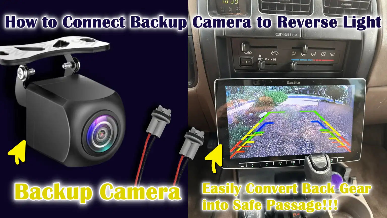
Yes, it is great convenience if you connect your vehicle’s backup camera to the reverse light, so that whenever you drive back your vehicle then it will automatically start giving you rear footage for safe parking and turning.
And, this is very reliable way to automate your safety, as it turns on automatically the moment you shift into reverse and switches off when you drive forward, that’s why that little thing makes the system fully automatic without extra switches and headache.
Basically, this setup works as the most of the passenger vehicles actually operates on a 12-volt electrical systems; and the reverse light actually receives the power only when the reverse gear is engaged.
Along with this, there’s safety studies and automotive safety organizations that shows that for reliable rear-visibility there are backup cameras that significantly reduces the blind spot problems behind the vehicles, specifically during the parking or reversing at the low speeds.
Not only this, there are many modern vehicles that uses this same wiring method but from the factory in-built, which is why it proves that it is reliable and long-term safety providing method.
So, just learn How to Connect Backup Camera to Reverse Light, so that you can ensure proper camera operation, avoid any electrical issues and protect the factory wiring as well.
Tools
| Items | Importance of Them |
|---|---|
| Backup Camera – Wired or Wireless | This is the main component that captures the rear view and sends it to the screen. Without the camera, the system cannot provide visibility while reversing. This improves safety by reducing blind spots. |
| Power and Video Cables | These cables connect the camera to both the power source and the display unit. Without the correct cables, the camera will not power on or display any images. They ensure the smooth flow of signals. |
| Wire Taps / T-Taps or Soldering Tools | These tools are needed to securely connect the camera’s power wire to the reverse light wire. A secure connection ensures a stable power supply. Loose connections can damage the camera. |
| Electrical Tape or Heat-Shrink Tubing | These materials prevent short circuits and protect the wires from moisture and dust. They also protect the wiring from damage caused by vibrations. Proper insulation enhances the safety of the system. |
| Multimeter or Test Light | These tools ensure that the wire receives power only when reverse gear is engaged. This prevents incorrect connections that could damage the camera or the car’s electronics. |
| Trim Removal Tools | These tools help you access the taillight wiring and install the cables correctly. They protect the clips and interior surfaces from damage. Using your hands or metal tools can cause breakage and damage. |
| Screwdrivers | These provide access to the reverse light area and help secure the camera mount. Without them, the panel and light cannot be properly removed. |
| Zip Ties | Zip ties ensure that wires do not hang loosely or come into contact with moving parts. Proper cable management improves the safety and durability of the installation. |
Now, At First Let’s Understand How the Backup Camera Gets Power from the Reverse Lights
1. How Reverse Lights Work Electrically
The reverse lights are directly connected to the vehicle’s transmission system via a reverse gear switch or sensor.
When the driver shifts the gear into reverse, this switch closes the electrical circuit, allowing power from the vehicle’s 12-volt battery to reach the reverse light bulbs.
When the gear is shifted out of reverse, the circuit opens again and the power is immediately cut off.
This on-off behavior makes the reverse light circuit very predictable and reliable.
Because the reverse lights only receive power when the vehicle is in reverse, they serve as a natural trigger signal for other devices, such as a backup camera.
2. Why the Backup Camera Only Turns On When Reverse Gear is Engaged
A backup camera only turns on in reverse because it shares the same power source as the reverse lights.
When the reverse gear is engaged, power flows to the reverse lights and simultaneously, the camera also receives power.
As soon as the gear is shifted to drive or neutral, the power supply is cut off and the camera automatically turns off.
This design prevents the camera from running continuously, saving energy and reducing wear and tear on the camera.
This automatic operation is the same method used in many factory-installed backup camera systems.
3. Understanding Positive and Negative Wires in a 12-Volt Vehicle System
Most passenger vehicles have a 12-volt direct current electrical system.
The positive wire carries electrical power from the battery to components such as lights and cameras.
The negative wire, also known as the ground wire, completes the circuit by connecting the component to the vehicle’s metal body.
The vehicle’s body itself acts as the return path for the electricity.
For the backup camera to function correctly, both a positive power wire from the reverse lights and a solid ground connection must be present.
If a connection is loose or missing, the camera may not turn on or function correctly.
4. Typical Voltage Range Found in Passenger Vehicles
Although vehicles are said to have a 12-volt system, the actual voltage can vary depending on operating conditions.
When the engine is off, the battery typically supplies approximately 12 to 12.6 volts.
When the engine is running and the alternator is charging, the voltage usually increases to between 13.5 and 14.5 volts.
Backup cameras and reverse lights are designed to operate safely within this range.
This stable voltage range ensures that the camera receives sufficient power to function correctly without damage, provided it is connected to the correct reverse light circuit.
How to Locate the Reverse Light and Safely Reach Out to its Wiring
1. Where are reverse lights typically located?
Reverse lights are typically located at the rear of the vehicle and are integrated into the taillight assembly.
In most cars, they appear as clear or white sections within the rear light cluster and illuminate only when the vehicle is in reverse gear.
Some vehicles have one reverse light, while others have two, depending on the design.
The reverse light wiring is usually located directly behind the taillight housing, inside the trunk or rear body panel area.
This location makes it one of the easiest lighting circuits to access without disturbing the vehicle’s larger systems.
2. How to safely remove interior trim or taillight housing
Accessing the reverse light wiring often requires removing interior trunk trim or the taillight housing.
Most interior panels are held in place with plastic clips or small screws that can be removed with gentle and even pressure.
Taillight housings are typically secured with bolts that can be accessed from inside the trunk or rear hatch.
Removing these components slowly and carefully helps prevent broken clips or damaged panels.
Using controlled force and the correct tools ensures the integrity of the vehicle’s interior and guarantees that everything can be reinstalled without looseness or rattling.
3. Identifying the correct reverse light wires
Once the reverse light area is exposed, several wires may be visible and not all of them belong to the reverse light circuit.
The correct reverse light wire will only receive power when the vehicle is in reverse gear and will be off at all other times.
This wire can be identified by turning on the ignition, engaging reverse gear and testing the wires.
The ground wire is typically connected to the vehicle’s body or a common grounding point.
Correct identification is crucial, as connecting to the wrong wire could damage the camera or affect other lighting functions.
4. Tips for Protecting Factory Wiring from Damage
Factory wiring is designed to last for many years, so it should be handled with care during installation.
Pulling the wires too forcefully, carelessly cutting the insulation, or sharply bending the wires can weaken them and lead to future electrical problems.
Connections should be made in a way that preserves the integrity of the original wiring as much as possible.
Properly supporting and securing the wires after making connections will prevent damage from vibrations during driving.
Careful handling ensures that the backup camera operates reliably and that there are no long-term issues with the vehicle’s electrical system.
How to Identify the Correct Reverse Light Power and Ground Wires
1. Using a Multimeter to Safely and Accurately Test Wires
A multimeter is one of the most reliable tools for identifying the correct reverse light wires because it shows the actual voltage present in the circuit.
When set to measure direct current voltage, it allows you to check which wire is receiving power when the vehicle is in reverse.
With the ignition on, one multimeter probe can be touched to a wire while the other probe is connected to a metal ground point.
A reading close to the vehicle’s operating voltage confirms that the wire is live.
This method reduces guesswork and helps avoid incorrect connections that could lead to electrical problems.
2. How to Correctly Confirm the Reverse Signal Wire
The reverse signal wire is the wire that receives power only when the reverse gear is engaged.
To confirm this, with the ignition on, the gear is shifted into reverse and the voltage of the wire is tested.
When the gear is shifted out of reverse, the voltage should drop back to zero.
This clear on-off behavior confirms the wire’s function.
If a wire shows continuous power in all gear positions, it is not the correct reverse signal wire and should not be used to power the backup camera.
3. Identifying the Correct Ground Connection for Stable Camera Operation
A proper ground connection completes the electrical circuit and allows the backup camera to function smoothly.
In most vehicles, the ground wire connects to the car’s metal body, which serves as a common return path for electricity.
A good ground point is typically a bare metal surface free of paint, rust, or dirt.
Testing the ground connection with a multimeter confirms continuity between the wire and the vehicle’s body.
A weak or faulty ground can cause the camera image to flicker or fail completely.
4. Understanding Common Wire Color Codes and Their Limitations
Many vehicles use common wire colors to help identify electrical circuits, but these colors are not universal.
Reverse light power wires are often light-colored, such as white or green, while ground wires are typically black or brown.
However, manufacturers may change color codes depending on the model, year, or market region.
Because of this variability, you should never rely solely on wire color.
Electrical testing should always be used to confirm the function of a wire before making any connections, even if the color appears correct.
How to Connect the Backup Camera’s Power Wire to the Reverse Light
1. Connect the Backup Camera’s Power Wire to the Reverse Light – Easy Method
Connecting the backup camera’s power wire to the reverse light begins with identifying the correct reverse light power wire using electrical testing.
Once confirmed, a small section of insulation is carefully removed from the reverse light wire without completely cutting it.
The backup camera’s power wire is then connected to this exposed section so that it receives power only when the reverse gear is engaged.
After the connection is made, it is gently pulled to ensure it is secure.
This process ensures the camera automatically turns on and operates only when reversing.
2. Wire Taps vs Soldering for Power Connections
Wire taps and soldering are two of the most common methods for connecting the backup camera’s power wire to the reverse light wire.
Wire taps clamp onto existing wires and create connections without cutting, making them quick and easy for beginners.
Soldering creates a strong electrical bond by melting solder onto the connected wires, providing superior conductivity and long-term reliability.
While wire taps are convenient, they can loosen over time if not installed correctly.
Soldered connections require more skill but are more resistant to vibration and electrical damage.
3. Secure the Power Connection for Long-Term Reliability
A secure power connection is crucial due to the constant vibration and movement vehicles experience while driving.
After the power wire is connected, it should be securely fastened in place to prevent it from moving or becoming loose.
Any excess wire length should be neatly routed along existing wiring paths.
This reduces strain on the connection point and prevents accidental disconnections.
A properly secured connection ensures consistent camera power and prevents sudden camera failure while reversing.
4. Insulation and Protection to Prevent Wiring Damage
Once the power connection is secure, it must be properly insulated to prevent short circuits and electrical interference.
The exposed metal parts of the connection should be completely covered to protect them from moisture, dust and heat.
Good insulation also prevents the wires from touching other metal parts of the vehicle, which could cause electrical malfunctions.
Properly protected wiring enhances safety and helps the backup camera function reliably for many years without any electrical problems.
How to Do Proper Grounding of the Backup Camera
1. Why Proper Grounding is Essential for Backup Camera Performance
Proper grounding is essential because it completes the electrical circuit, allowing the backup camera to function smoothly and reliably.
Without a strong ground connection, electrical current cannot flow correctly, even if the power wire is properly connected.
Poor grounding is one of the most common causes of camera problems, such as image flickering, delayed startup, or complete failure.
Vehicles use the metal body as a common return path for electricity, so a weak ground can affect signal quality.
A strong ground connection ensures stable voltage, clear video output and consistent camera operation every time reverse gear is engaged.
2. Best Grounding Points on the Vehicle Body
The best grounding points are solid metal parts that are directly connected to the vehicle’s body.
These points are often found near the taillights, such as factory grounding bolts, metal brackets, or existing ground wires connected to the chassis.
Using a nearby grounding point minimizes wire length, improving electrical stability.
The metal surface should be part of the vehicle’s frame, not a plastic or painted panel.
Choosing the correct grounding point ensures the camera receives a clean and uninterrupted ground signal.
3. How to Properly Clean and Prepare the Ground Point
Before attaching the ground wire, the metal surface must be clean and free of paint, rust, grease, or dirt.
Paint and rust act as insulators that impede the flow of electricity.
Cleaning the surface exposes bare metal, allowing the ground wire to make full contact.
The ground wire should be securely fastened with a tight bolt or screw to prevent it from loosening over time.
Proper preparation of the ground point minimizes resistance and helps maintain long-term electrical reliability.
4. Testing Ground Continuity to Ensure a Reliable Connection
Ground continuity testing verifies that the ground connection is functioning as expected.
This is done by checking whether electricity can flow easily between the ground point and the vehicle’s body.
A successful test result indicates a strong connection with very low resistance.
If the continuity is poor or intermittent, the ground point should be cleaned or replaced.
Checking the continuity ensures that the backup camera will operate without flickering, delays, or signal loss during normal vehicle use.
How to Route the Video Cable from the Camera to the Display Unit
1. Securing Cable Routing Paths Inside the Vehicle
Securely routing the video cable is crucial as this cable carries the camera image from the rear of the vehicle to the display screen.
The safest routes typically follow the factory wiring paths, which are already designed to protect electrical cables from heat, vibration and damage.
These paths often run behind interior panels, under door sills and along the sides of the cabin.
Following existing wiring routes minimizes the potential for interference and ensures a clean installation.
Using factory routes also simplifies future repairs and maintains a neat, professional appearance.
2. Avoiding Sharp Edges and Moving Parts
Sharp metal edges and moving parts can easily damage the video cable over time.
When a cable rubs against sharp edges, the outer insulation can wear down, exposing the inner wires, which can lead to signal loss or short circuits.
Moving parts such as seat rails, pedals, hinges and steering components can pinch or cut the cable while the vehicle is in motion.
Keeping the cable away from these areas protects it from stress and vibration.
Proper clearance ensures long-term reliability and prevents sudden camera malfunctions.
3. Routing the Video Cable Through the Trunk, Cabin and Dashboard
The video cable typically starts near the camera at the rear of the vehicle and runs through the trunk area before entering the cabin.
From there, it is routed along the interior side panels or floor edges towards the dashboard.
Inside the dashboard, the cable is carefully routed to the display unit or head unit input.
Smooth routing avoids tight bends and stress on the cable.
A well-planned routing path ensures strong signal quality and prevents sudden disconnections while driving.
4. Securing Cables to Prevent Rattling or Damage
Once the cable is routed, it’s crucial to secure it so it doesn’t move while the vehicle is in motion.
Loose cables can rattle, rub against surfaces, or become dislodged over time.
Securing the cable keeps it stable and reduces stress on the connectors.
Proper support also prevents damage from vibrations, which are common in vehicles.
A securely routed cable ensures that the backup camera continues to provide clear images without any noise or interruptions.
How to Connect the Camera to the Head Unit or Monitor
1. Understanding the RCA Video Connection Between the Camera and Display
Most backup cameras transmit their video signal via an RCA cable, a common round connector designed to carry video data with minimal interference.
This cable connects directly from the camera to the video input on the head unit or monitor.
The connection must be secure to ensure a stable video signal while driving.
Loose RCA connections can result in a black screen, flickering images, or signal dropouts.
Properly connecting the RCA cable ensures that the live camera image is displayed clearly and instantly when reverse gear is engaged.
2. Connecting the Reverse Trigger Wire – If Required
Some head units and monitors require a separate reverse trigger wire to tell the screen when to switch to the camera view.
This wire carries a small electrical signal from the reverse light circuit to the display unit.
When reverse gear is selected, the trigger wire sends a voltage to the head unit, instructing it to display the backup camera image.
Without this signal, the camera may be powered on, but the screen may not switch automatically.
Correctly connecting the trigger wire ensures a smooth and automatic switch to the reverse camera view.
3. Differences Between Factory Head Units and Aftermarket Displays
Factory head units are often pre-wired to recognize the reverse signal and may already have a dedicated camera input.
In many cases, they require specific connection points or adapters designed for the vehicle model.
Aftermarket displays are generally more flexible and clearly labeled for camera and reverse trigger connections.
However, aftermarket units also require correct wiring to function properly.
Understanding these differences helps avoid confusion during installation and ensures compatibility between the camera and the display system.
4. Double-checking all connections before final use
Before completing the installation, every connection should be carefully checked to ensure it is secure and correct.
Power wires should be firmly connected, video cables should be fully inserted and ground connections should be tight and clean.
Testing the system before closing the panel allows for easy troubleshooting of any issues.
This final check minimizes the likelihood of future problems and ensures that the backup camera activates reliably and displays a clear image whenever reverse gear is selected.
How to Test the Backup Camera Before Final Assembly
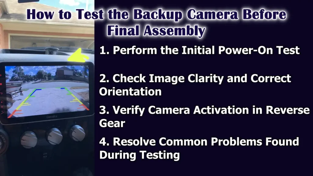
1. Perform the Initial Power-On Test
The initial power-on test confirms that the backup camera is receiving power and responding correctly to the reverse signal.
With the ignition on, the gear is shifted into reverse to check if the camera activates and the display turns on.
This test should be performed before reattaching any panels to allow for easier adjustments.
If the camera does not turn on, it usually indicates a problem with the power, ground, or trigger connection.
Performing this test early saves time and avoids repeated disassembly later.
2. Check Image Clarity and Correct Orientation
Once the camera is on, the image quality should be carefully checked.
The picture should be clear, stable and free of flickering or distortion.
The image orientation should also be correct so that left and right movements on the screen appear natural.
Some cameras allow for adjusting the angle or settings to correct the alignment.
Verifying clarity and orientation ensures that the camera provides accurate visual information while reversing.
3. Verify Camera Activation in Reverse Gear
The backup camera should only activate when the reverse gear is engaged and should immediately turn off when shifting out of reverse.
This confirms that the camera is correctly connected to the reverse light circuit.
Delayed activation or failure to turn off usually indicates an incorrect power source or trigger wire connection.
Correct activation behavior ensures that the system operates automatically and does not distract the driver during normal driving.
4. Resolve Common Problems Found During Testing
If any problems arise during testing, they should be addressed before final assembly.
A black screen may indicate a loose video cable or a missing trigger signal.
Flickering or unstable images often indicate a poor ground connection.
A lack of power usually means the reverse light wire is not properly connected.
Identifying and fixing these problems at this stage ensures that the backup camera will function reliably once the vehicle is fully reassembled.
Read More:
How to Solve Common Backup Camera Connection Problems
1. Backup Camera Not Turning On
The most common reason a backup camera doesn’t turn on is a problem with the power or ground connection.
This usually happens when the camera isn’t connected to the correct reverse light wire or if the ground point is weak or loose.
The camera only needs power when the reverse gear is engaged, so testing the reverse light circuit is crucial.
If the camera remains off, checking the voltage on the power wire can confirm whether power is reaching the camera.
Correcting these connections usually resolves the issue and allows the camera to function correctly again.
2. Image Flickering or No Video Signal
Image flickering or a complete loss of video signal often indicates an unstable connection.
Loose RCA connectors, poor grounding, or faulty cables can disrupt the video signal while driving.
Electrical noise from other vehicle systems can also affect poorly routed cables.
Ensuring the video cable is securely connected and routed away from high-power wires helps minimize signal problems.
A stable connection results in a clear and consistent camera image.
3. Camera Activation Delay
Activation delays occur when the camera or display takes too long to turn on after engaging reverse gear.
This is often due to a weak power supply, incorrect trigger wire connection, or slow signal processing by the head unit.
If the reverse trigger wire isn’t receiving voltage immediately, the display may hesitate before switching to the camera view.
Verifying that the camera is receiving power directly from the reverse light circuit usually improves response time.
Instant activation is indicative of proper wiring.
4. Interference or Poor Camera Image
Interference or poor image quality can manifest as lines, static, or blurry images on the screen.
This problem often occurs when the video cable runs too close to high-current wires, such as power cables or alternator lines.
Poor grounding can also generate electrical noise and degrade image quality.
Rerouting the cable and improving the ground connection usually resolves these interference issues.
A clean signal path ensures that the camera delivers accurate and reliable images.
What are the Safety Tips and Best Practices for Having Reliable Installation
Even, there’s study in Accident Analysis & Prevention that researched on how backup cameras and sensor systems effective improve what a driver can see behind a vehicle, specifically regarding the small children it can be really beneficial, as in the research itself they found out that average blind zones behind the vehicles literally shrank by around 90% whenever these kinds of technologies were used, as you don’t have to rely on the mirrors and direct glances alone. So, the blind zones are a key factor in backover accidents, that why you when you connect your backup camera via the reverse light circuit then it actually helps you to maintain the consistent visibility every time the vehicle is in reverse gear.[¹]
1. Battery Disconnection Precautions Before Installation
Disconnecting the vehicle’s battery before working on electrical wiring is a crucial safety step.
This prevents accidental short circuits that could damage electronic components or blow fuses.
Disconnecting the battery also reduces the risk of sparks when handling exposed wires.
In most vehicles, simply disconnecting the negative battery terminal is sufficient to interrupt the electrical flow.
Taking this simple precaution helps protect both the installer and the vehicle’s electrical system.
2. Protecting Wiring from Moisture and Heat Damage
Vehicle wiring is exposed to fluctuating temperatures and moisture, specially near the rear of the car.
Moisture can cause corrosion inside wire connections, leading to weakened or failed electrical flow over time.
Heat from the exhaust or engine can soften insulation and damage wires if they are routed too close.
Proper insulation and careful wiring help protect the wires from environmental damage.
Long-term protection ensures the backup camera operates reliably in all weather conditions.
3. Avoiding Overloading the Reverse Light Circuit
The reverse light circuit is designed to power light bulbs, not heavy electrical loads.
Backup cameras are low-power devices, but incorrect wiring or additional accessories can overload the circuit.
Overloading can blow fuses or cause the reverse lights to dim.
Connecting only the camera to the reverse light circuit helps maintain safe operation.
Understanding the circuit’s electrical limitations prevents damage and ensures stable camera performance.
Understand, Difference Between Wired and Wireless Backup Camera Power & Their Considerations
1. How Wireless Backup Cameras Still Utilize Reverse Light Power
Even though wireless backup cameras don’t use long video cables, they still require power to operate.
Most wireless cameras draw power by connecting directly to the reverse light circuit at the rear of the vehicle.
This ensures the camera automatically activates only when the reverse gear is engaged.
Wireless simply refers to how the video signal is transmitted to the display, not how the camera receives power.
Using the reverse lights as a power source ensures automatic operation and prevents unnecessary battery drain.
2. Differences in Wiring Complexity Between Wired and Wireless Systems
Wired backup cameras require running both a power cable and a video cable from the rear of the vehicle to the display at the front.
This process is more time-consuming and requires careful routing of the wiring through the cabin.
Wireless cameras reduce the amount of necessary video wiring because the image is transmitted via a wireless signal.
However, both systems still require proper power and ground connections at the rear.
While wireless systems may seem simpler, they still require careful electrical work to function correctly.
3. Reliability and Signal Stability Comparison
Wired backup cameras are generally more reliable because the video signal travels directly through a cable connection.
This reduces the risk of interference and signal loss.
Wireless cameras rely on radio signals, which can be affected by other electronic devices, the vehicle’s structure, or distance.
In some cases, wireless systems may experience delays, image freezing, or interference.
Understanding these differences allows users to choose a system that meets their reliability expectations.
4. Choosing the Right Backup Camera Setup for Your Vehicle
The choice between wired and wireless backup cameras depends on the vehicle design and personal preference.
For larger vehicles, wired systems may be more advantageous because the signal is stronger and more stable over longer distances.
Installing wireless systems in smaller vehicles can be quite easy and performance is generally good.
Ease of installation, signal reliability and consideration of the vehicle’s layout ensure that the camera system functions smoothly.
Choosing the right setup provides both enhanced safety and long-term satisfaction.
How to Finally Inspect Them and Reassemble
1. Securing All Parts for Long-Term Use
Once the backup camera system has been tested and confirmed to be working correctly, all parts should be secured.
The camera mount should be tightened securely to prevent movement due to vibrations or rough roads.
The wiring should be routed in a way that avoids excessive strain on the connection points.
Loose parts can lead to future problems, such as image distortion or electrical malfunctions.
Properly securing everything ensures the system remains stable and reliable over time.
2. Reinstalling Trim and Panels Correctly
After securing the wiring and camera, the interior trim pieces and taillight housing should be carefully reinstalled.
Panels should be properly aligned before installation to prevent broken clips or gaps.
Screws and bolts should be tightened evenly to ensure a proper fit.
Correct reassembly prevents rattling noises while driving and maintains the vehicle’s interior in its original condition.
Taking the time on this step results in a factory-like finish.
3. Performing a Final Functional Check
A final functional check confirms that everything is working correctly after reassembly.
The ignition should be turned on and the vehicle should be put into reverse gear to ensure the camera activates immediately.
The image should appear clear, properly aligned and stable on the display.
Checking the operation after reassembly ensures that no wires were damaged during panel installation.
This step verifies that the installation is complete and reliable.
4. Ensuring a Clean and Professional Factory-Like Finish
A clean, factory-like finish means the installation looks neat and original, with no visible wires or loose parts.
Wiring should be hidden behind panels and routed through factory pathways.
The camera should be mounted straight and centered for optimal viewing.
A clean finish not only enhances the appearance but also protects the system from damage.
This level of finish indicates a meticulous and professional installation.
Conclusion – How to Connect Backup Camera to Reverse Light
So, when you properly connect your vehicle’s backup camera with the reverse light that actually makes a safety system that works automatically every time you take your vehicle reverse.
Basically, this method allows the camera to turn on automatically only when the vehicle is in reverse, improving safety, reducing distractions and preventing unnecessary power consumption.
And, by carefully identifying the correct reverse light wire, establishing a secure power and ground connection, routing the cables safely and testing the system before final assembly, you ensure stable performance and long-term reliability.
Without a doubt, a proper grounding and insulation protect the system from common electrical issues such as flickering, delayed activation and signal loss.
A properly installed backup camera not only makes parking easier but also adds a crucial layer of safety for passengers, pedestrians and surrounding vehicles.
Now, it is time to ask questions in the comment box for more information.
Frequently Asked Questions
Q1. What is the easiest way to power a backup camera using the reverse lights?
Answer: The easiest and most reliable way to power a backup camera is to connect its power wire directly to the reverse light circuit. The reverse lights only receive power when the vehicle is in reverse, meaning the camera will automatically turn on at the correct time. You’ll need to identify the correct reverse light wire, securely connect the camera’s power wire, make a proper ground connection and then run the video cable to your display. This method eliminates the need for extra switches or manual controls and ensures the camera reliably operates whenever you shift into reverse.
Q2. Do I need any special tools to connect the backup camera to the reverse lights?
Answer: You don’t need many specialized tools, but a few basic items will make the job much easier and safer. A multimeter or test light is helpful for identifying the correct reverse light wire and wire taps or soldering tools are needed to securely connect the power wire. Electrical tape or heat-shrink tubing will secure the connections, while screwdrivers and trim removal tools will help you safely access the wiring. These tools ensure the connections are robust, secure and professional-looking.
Q3. How do I identify the correct reverse light wire for the camera?
Answer: The correct reverse light wire is the one that only receives power when the vehicle is in reverse. You can locate this wire by using a multimeter or test light while the car is in reverse. This wire typically comes directly from the taillight assembly and common colors include white, green, or yellow, although this can vary depending on the vehicle. Confirming the correct wire is crucial, as connecting to the wrong wire could damage the camera or affect other electrical systems in the car.
Q4. Where should I ground the backup camera for best performance?
Answer: The ground wire should be connected to a solid metal point on the vehicle’s body, which serves as the return path for the electricity. A bare metal surface near the rear light assembly is usually the best location. Ensure the surface is free of paint, rust, or dirt to guarantee full contact with the wire. Proper grounding ensures the camera operates without flickering or signal loss and prevents common electrical problems such as unstable images or delayed activation.
Q5. Can I use this method for both wired and wireless backup cameras?
Answer: Yes, both wired and wireless cameras can use the reverse lights as their power source. Wired cameras require both power and video cables running to the display, while wireless cameras transmit the video signal via a wireless transmitter but still require power from the reverse lights. Using the reverse lights as the power source allows both types of cameras to operate automatically and prevents battery drain when the vehicle is not in reverse.
Q6. What are the most common problems when connecting a backup camera to the reverse lights?
Answer: The most common problems include the camera not turning on, image flickering, delayed activation, or poor video quality. These are usually caused by loose power connections, poor grounding, or incorrect wiring. Sometimes the RCA video cable can be loose or routed too close to high-power wires, causing interference. Testing the camera before reassembling the panels and properly securing all connections can prevent these problems and ensure smooth, reliable operation.
Q7. Is it safe to connect a backup camera to the reverse lights myself?
Answer: Yes, it is safe if you follow the correct steps and take precautions. Always disconnect the vehicle’s battery before working on the wiring to avoid short circuits. Identify the correct reverse light wire, secure the power and ground connections and carefully route the cables to protect them from sharp edges or moving parts. If you follow these safety procedures, the installation can be done reliably at home. For more complex vehicles or advanced electronic systems, it may be advisable to seek professional assistance.
Q8. Will connecting the backup camera to the reverse lights affect my vehicle’s lights?
Answer: When done correctly, connecting the backup camera to the reverse lights will not affect the lights. Backup cameras draw very little power compared to the bulbs, so the reverse lights will function normally. It’s important to avoid connecting other devices that exceed the circuit’s capacity. Proper connection ensures the camera operates automatically without dimming or overloading the reverse lights.
Q9. How can I test the backup camera after connecting it to the reverse lights?
Answer: After connecting the camera, test it by turning on the ignition and putting the vehicle in reverse. The camera should activate immediately and a clear image should appear on the display. Check that the image is properly aligned and stable and that there is no flickering or interference. If the camera does not respond correctly, check the power and ground connections, the reverse trigger wire and the video cable.
References:
[1] Visibility of children behind 2010–2013 model year passenger vehicles using glances, mirrors and backup cameras and parking sensors
https://www.sciencedirect.com/science/article/abs/pii/S0001457514000104

Guys, I’m a car audio enthusiast and customization expert and I love clear sound and clean installation. Plus, I have spent years helping people build their dream audio setups. And whenever I’m working on cars, I probably listen to music and thinks about the next big upgrade.